

Single Axis Urea Crusher
npk bulk blending machine > Single Axis Urea Crusher
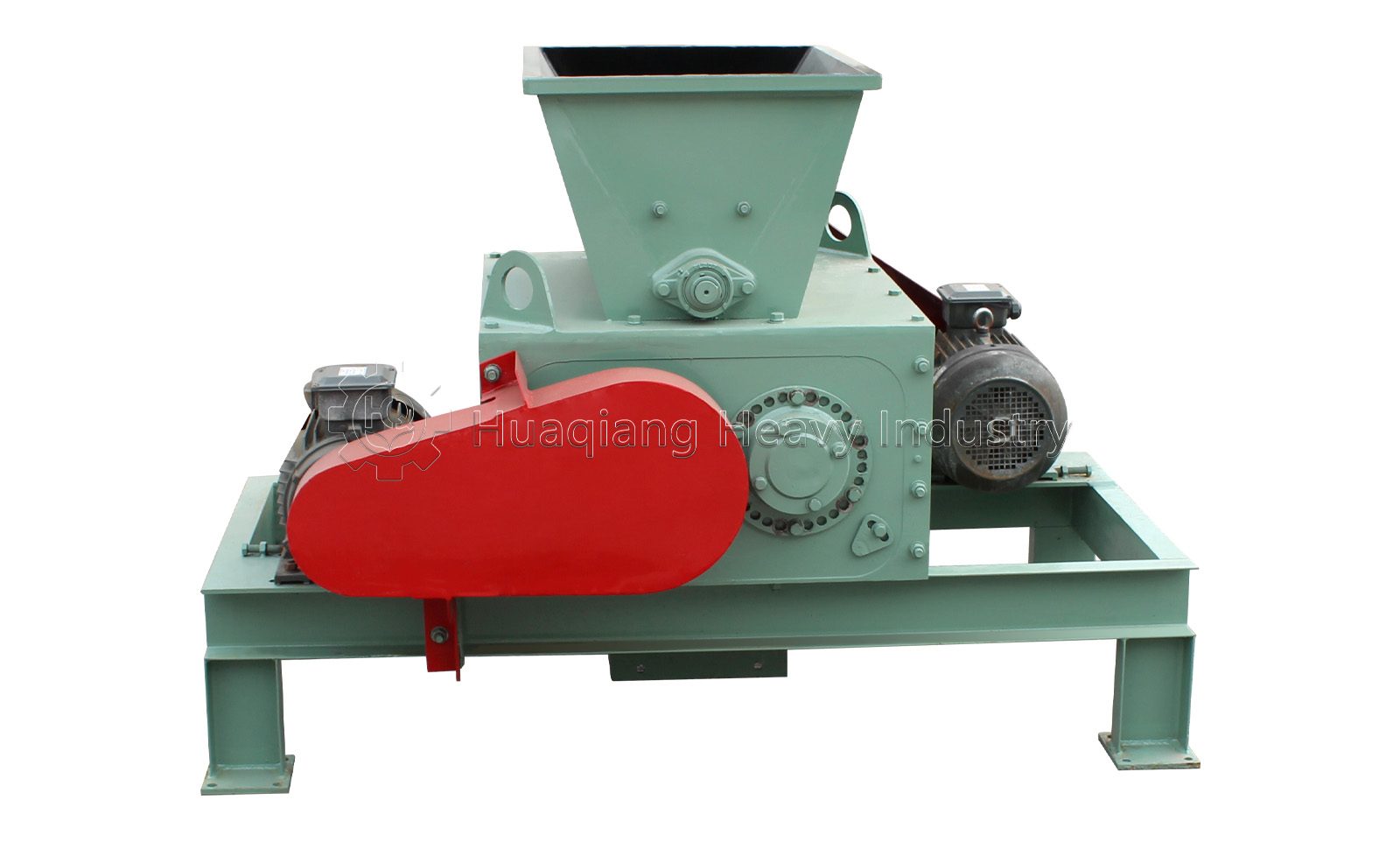
Single Axis Urea Crusher
The single axis urea crusher is a specialized piece of equipment designed for the pretreatment of fertilizer raw materials—specifically those prone to deliquescence and caking—within production lines for compound fertilizers (NPK), organic-inorganic compound fertilizers, and water-soluble fertilizers. The equipment focuses on the shearing and breaking down of granular urea that has caked due to moisture or hardened at ambient temperatures, aiming to overcome the common challenges faced by traditional crushing machinery when processing heat-sensitive materials like urea.
As a widely used straight nitrogen fertilizer in agriculture, urea presents unique challenges for crushing due to its physical properties; it is highly hygroscopic and readily soluble. During storage and stockpiling, it easily cakes under the influence of moisture and pressure, rendering large urea lumps unsuitable for direct use in batch mixing, water-soluble fertilization, or mechanical spreading. Standard crushing equipment faces three major pain points when processing urea: first, over-crushing—urea is brittle, and high-speed impact easily generates excessive ultra-fine dust, leading to raw material waste and creating explosion risks due to dust accumulation in the workshop; second, thermal melting—with a melting point of approximately 132–133°C, the frictional heat generated during high-speed crushing can easily soften or even melt the surface of urea granules, causing material to stick to walls and clog screens, thereby necessitating frequent shutdowns for cleaning; and third, wall adhesion and clogging—urea becomes sticky after absorbing moisture, leading to material buildup and scaling inside the crushing chamber, which severely disrupts continuous operation.
Structural composition of the equipment
The single axis urea crusher features a specialized structural design optimized for the characteristics of urea granules—specifically their tendency to absorb moisture, adhere to surfaces, and cause corrosion. The machine comprises the following core components:
(I) Feeding System: Includes a feed hopper and a toothed lump-breaking roller at the inlet. The inlet is equipped with a toothed roller to break up lumps, ensuring continuous operation without clogging, even if minor agglomeration occurs. An adjustable inlet mechanism allows for flexible control of production volume to meet varying operational needs. Hard objects such as metal or stones must be removed from the material prior to feeding to prevent damage to the single Axis assembly.
(II) Single Axis Crushing Chamber: This is the equipment's core processing chamber, consisting of an upper casing, a lower casing, crushing plates, and an arc-shaped impact plate. The chamber features a fully sealed design to prevent dust leakage. The inner walls are constructed from corrosion-resistant materials (such as 304 stainless steel) and treated with polished, anti-stick coatings; this design resists the mildly alkaline corrosion caused by dissolved urea while effectively minimizing material adhesion. Certain models feature an anti-stick Teflon coating combined with an internal cleaning scraper to continuously remove residual material from the chamber walls. Key components—including the crushing chamber and single Axis assembly—incorporate anti-corrosion and anti-clogging designs to prevent material buildup and agglomeration, ensuring stable, continuous operation.
(III) Single Axis Rotor Assembly: This is the primary working component, consisting of a main shaft, end discs, and wear-resistant cutter heads (or hammer blades). Multiple rows of high-strength alloy hammer blades or wear-resistant cutter teeth are secured to the rotor via keyed connections. The blades are typically made from 65Mn spring steel or Cr12MoV alloy tool steel, heat-treated to enhance wear resistance and impact toughness. The rotor assembly comprises the main shaft, end discs, and wear-resistant cutter heads. The machine operates by rotating the single Axis rotor at a constant speed; specialized arc-shaped hammer heads gently break apart urea lumps. Compared to twin Axis or multi Axis crushers, the single Axis urea crusher offers a compact structure, a smaller footprint, and lower power consumption. (IV) Concave Plate and Gap Adjustment Mechanism: The gap between the roller and the concave plate can be flexibly adjusted within the range of 3–12 mm. The gap size directly determines the degree of material pulverization. The output particle size is adjustable, allowing for the production of uniform small granules suitable for BB fertilizer blending or fine powders required for water-soluble fertilizers. The aperture of the bottom screen plate can be changed as needed; common sizes range from Φ3 mm to Φ10 mm.
(V) Air-Cooling Heat Dissipation System: To address the heat-sensitive nature of urea, the equipment features an air-cooling structure. This effectively controls the temperature rise during pulverization (typically ≤40°C), preventing urea melting, caking, or nitrogen loss due to frictional heat. The machine casing is equipped with heat dissipation fins or a natural air-cooling design.
(VI) Transmission and Drive System: Comprises an electric motor, V-belts, pulleys, and a protective guard. The motor drives the main shaft via V-belts, achieving speeds of up to 1,440 rpm. It utilizes a national-standard, pure-copper, energy-efficient motor characterized by low noise and low energy consumption. Equipped with a variable-frequency speed control system, operators can flexibly adjust the equipment speed based on the degree of material caking and the desired output particle size.
(VII) Discharge and Sealing System: Includes the discharge outlet and the main shaft sealing assembly. The unit features a fully enclosed, integrated body design with no open dust-emitting ports. The main shaft utilizes a dual-protection sealing system—combining labyrinth seals and packing seals—to completely prevent fine powder leakage and bearing contamination. The equipment features a rational structural design free of complex "dead zones" where material might accumulate, making daily disassembly, cleaning, and maintenance highly convenient.
The working principle of the equipment
The working principle of the single axis urea crusher relies on the synergistic effect of "low-speed shearing, grinding/pulverizing, and air-cooled heat dissipation."
Feeding and Primary Crushing Stage:Urea granules or lumps are introduced through the feed inlet, where a toothed roller performs initial crushing on large lumps. A feed adjustment mechanism allows for flexible control of production throughput.
Low-Speed Shearing and Impact Stage:Upon entering the fully sealed crushing chamber, the material is processed as an electric motor drives the single shaft at high speed via V-belts. Wear-resistant tooth bars on the shaft interact with a concave plate to crush the urea through grinding and shearing actions. Inside the machine, urea particles first impact the chamber walls and baffles for initial breakage, then are ground into powder by the action of the tooth bars against the concave plate. Unlike conventional high-speed impact crushers, this unit operates at a moderate speed, relying primarily on shearing and compression. It features a custom single-shaft spiral shearing design that eschews high-speed impact in favor of low-speed kneading, shearing, and breaking to process caked fertilizer. Through the combined action of shearing, kneading, and breaking, hardened urea lumps are progressively reduced to fine particles. This enables precise crushing that preserves uniform, medium-to-small granules while effectively preventing the excessive pulverization that creates airborne dust.
Air-Cooled Heat Dissipation and Temperature Control:To address the heat-sensitive nature of urea, the equipment incorporates an air-cooling system that effectively limits temperature rise during crushing (typically ≤40°C). The chamber temperature is generally maintained within 10–15°C above ambient levels, preventing urea particles from becoming sticky due to heat and clogging the screen. The rotor's linear speed can be adjusted based on urea characteristics, complemented by cooling fins on the casing or natural air cooling.
Screenless Discharge Stage:The machine utilizes a screenless, open-flow design; discharge fineness is controlled by adjusting the mechanical clearance. Material meeting size specifications is discharged rapidly, while coarse particles automatically recirculate for secondary crushing. Once the material reaches the desired particle size, it is discharged. This screenless design completely eliminates the risk of clogging or machine stalling caused by moist, caked fertilizer. The entire unit features a fully sealed design, ensuring no dust leakage.
Equipment troubleshooting
Excessive pulverization temperature and urea melting: A low-speed shear-based pulverization process is employed to maintain low temperatures throughout. The equipment features a custom single-shaft spiral shear mechanism, eschewing high-speed impact crushing in favor of low-speed kneading, shearing, and breaking to process caked fertilizer. An air-cooling system limits the temperature rise to ≤40°C, and the rotor's linear speed can be adjusted downward based on urea's specific properties.
Material clogging and wall adhesion: The inner walls of the pulverization chamber are made of corrosion-resistant materials like 304 stainless steel, featuring polished surfaces and anti-stick coatings. The chamber structure is specifically optimized to handle urea's tendency to cake and adhere due to moisture absorption. A toothed roller at the inlet breaks up lumps, preventing blockages even with minor caking, while the screenless, open-flow design completely eliminates clogging issues.
Over-pulverization and excessive dust: A single-shaft, low-speed, gentle pulverization mechanism uses specialized curved hammers to softly break apart caked urea, relying primarily on shearing and compression. This allows for precise crushing that preserves uniform, small-to-medium-sized granules. The machine features a fully enclosed, integrated housing with no open dust-emission points.
Reduced output: Regularly inspect blades for wear and replace them promptly; clear obstructions from screen plates; and check belt tension.
Abnormal equipment vibration: Replace blades in sets to maintain rotor balance; monitor bearing temperature rise and seal integrity.
All Services
Let's Start a Project
Call us directly, submit a sample or email us!
Office Address:
NO.313, Wanshan Road, Xingyang City, Zhengzhou City, Henan Province, China
Contact With Us
Call us: +86-18703630069
Email
[email protected]